
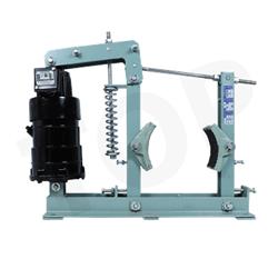
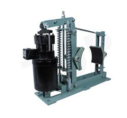
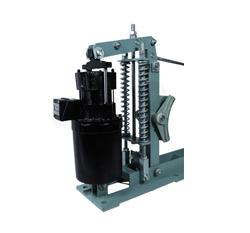
Mill Duty Thruster Brake
Aligning And Setting of Brake:
Rotary geared type limit switches are used on the control circuit of reversing drives so as to limit their rotation/movement with pre-determined position. The function of limit switch is to stop the mechanism at different combinations with totally enclosed in IP-55 degree of protection with N.O. and N.C. contracts combination. Gear ration available are 48:1 and 60:1
Setting of Brake Shoes:
The shoe setting screws on both shoes are to be adjusted when brake is released. Both shoes must be set such that the clearance between the drum and the brake lining at the top & bottom corners of the shoes is equal.
The clearance measurement can be done with a feeler gauge or with shims of known thickness. This setting ensures that the shoes will not drop down under gravity and the brake drum will run without any drug when the brake is released.
Adjusting Braking Torque:
Toadjust the braking torque, the pre-tension of the compression spring is to be adjusted such that the required braking torque is obtained. Adjusting the top locking nuts of the tie-rod of the compression spring results in increasing (when the nuts are tightened clockwise ) or reducing (When the nuts are slacked by turning them in anti-clock-wise direction) the pre-tension of the spring.
The adjustment of the braking torque is very critical. Too low braking torque will result in smooth stoppage of load and delayed braking and will also risk of load slippage when heavy loads are handled. Too high values of braking torque results in rapid and abrupt stoppage resulting in heavy jerk & noise. The mechanical jerk may induce undesired stresses resulting in premature breakage of intemediate linkages like pins, bolts screws etc. For most applications, braking torque of the drive motor is sufficient. However for some specific applications (like long/ cross travel motors in cranes) lower values of 80 to 150% would be sufficient. Some applications like heavy lifting machines,quick stoppage is critical,braking torque of 250 to 350% are also used.
To adjust the brake the locknut and the nut of the compression spring tie rod are first slackened and then the spring tension is adjusted by tightening the nut clockwise (view form top). Increased spring tension increases the braking torque.
Brake Model |
Brake Drume Dia. Mm (D) |
Brake Torque |
Thruster Details |
C |
N |
P |
Q |
Mass kg. |
||||
vv |
vv |
kg-m |
N-m |
Model |
Force kg. |
Force (N) |
Stroke (S) |
vv |
vv |
vv |
vv |
vv |
MDT-100-15 |
100 |
5 |
50 |
ST 515 |
15 |
150 |
51 |
135 |
280 |
105 |
85 |
17 |
MDT-150-15 |
150 |
7.5 |
75 |
ST 515 |
15 |
150 |
51 |
135 |
280 |
105 |
85 |
20 |
MDT-160-15 |
160 |
7.5 |
75 |
ST 515 |
15 |
150 |
51 |
135 |
280 |
105 |
85 |
20 |
MDT-200-15 |
200 |
16 |
160 |
ST 515 |
15 |
150 |
51 |
135 |
280 |
105 |
85 |
27 |
MDT-100-18 |
100 |
6 |
60 |
ST 520 |
18 |
180 |
51 |
159 |
349 |
110 |
90 |
17 |
MDT-150-18 |
150 |
9 |
90 |
ST 520 |
18 |
180 |
51 |
159 |
349 |
110 |
90 |
20 |
MDT-160-18 |
160 |
9 |
90 |
ST 520 |
18 |
180 |
51 |
159 |
349 |
110 |
90 |
20 |
MDT-200-18 |
200 |
20 |
200 |
ST 520 |
18 |
180 |
51 |
159 |
349 |
110 |
90 |
27 |
MDT-200-34 |
200 |
32 |
200 |
ST 535 |
34 |
340 |
51 |
159 |
349 |
110 |
90 |
27 |
MDT-250-18 |
250 |
35 |
350 |
ST 520 |
18 |
180 |
51 |
159 |
349 |
110 |
90 |
30 |
MDT-250-34 |
250 |
42 |
420 |
ST 535 |
34 |
340 |
51 |
171 |
444 |
138 |
110 |
30 |
MDT-300-18 |
300 |
42 |
420 |
ST 520 |
18 |
180 |
51 |
159 |
349 |
110 |
90 |
70 |
MDT-300-34 |
300 |
62 |
620 |
ST 535 |
34 |
340 |
51 |
171 |
444 |
138 |
110 |
70 |
MDT-400-34 |
400 |
90 |
900 |
ST 535 |
34 |
340 |
51 |
171 |
444 |
138 |
110 |
85 |
MDT-400-46 |
400 |
110 |
1100 |
ST 545 |
46 |
460 |
51 |
215 |
508 |
152 |
124 |
95 |
MDT-400-68 |
400 |
170 |
1700 |
ST 870 |
68 |
680 |
76 |
215 |
508 |
152 |
132 |
110 |
MDT-500-46 |
500 |
190 |
1900 |
ST 545 |
46 |
460 |
51 |
215 |
444 |
152 |
110 |
125 |
MDT-500-68 |
500 |
290 |
2900 |
ST 870 |
68 |
680 |
76 |
215 |
508 |
152 |
124 |
135 |
MDT-500-114 |
500 |
485 |
4850 |
ST 8110 |
114 |
1140 |
76 |
215 |
508 |
152 |
124 |
135 |
MDT-600-68 |
600 |
350 |
3500 |
ST 870 |
68 |
680 |
76 |
215 |
508 |
125 |
124 |
190 |
MDT-600-114 |
600 |
580 |
5800 |
ST 8110 |
114 |
1140 |
76 |
215 |
508 |
152 |
124 |
190 |
")
