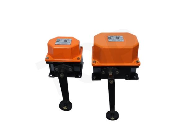
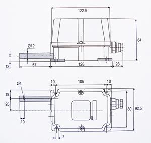
Limit Switches
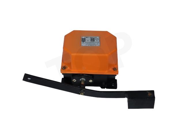
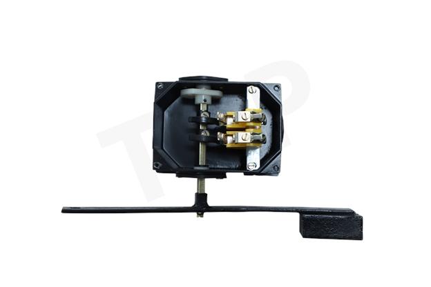
Lever Type Limit Switch
Body Material: |
Powder Coated Aluminium die cast |
Degree of Protection: |
IP-55 Confirming to IS- 13947 (Part-1)1993 |
Mounting Position: |
Floor |
Cable Entries: |
2, 3/4" Conduit |
No. of Contact: |
2/3/4 |
Contact: |
Double break silver cadmium |
Wire Connection: |
Screw terminal |
Rated Voltage Insulation: |
500 V.A.C. |
Thermal Test Current: |
10/40 Amps. |
Operation: |
720/hour |
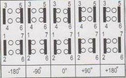
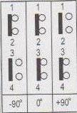
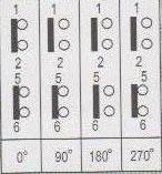
Switching diagram:
|
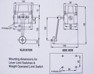
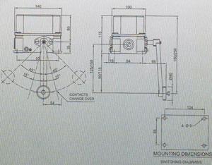
Weight Operated Switch
Body Material: |
Powder Coated Aluminium die cast |
Degree of Protection: |
IP-55 Confirming to IS- 13947 (Part-1)1993 |
Mounting Position: |
Floor |
Cable Entries: |
2, 3/4" Conduit |
No. of Contact: |
2/3/4 |
Contact: |
Double break silver cadmium |
Wire Connection: |
Screw terminal |
Rated Voltage Insulation: |
500 V.A.C. |
Thermal Test Current: |
10/40 Amps. |
Operation: |
720/hour |
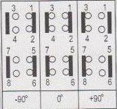
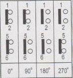
Switching diagram:
| CWLS/1SH/2 | ||||||||||
| ||||||||||
| CWLS/1SH/1 | ||||||||||
|
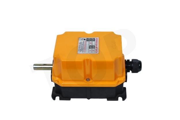
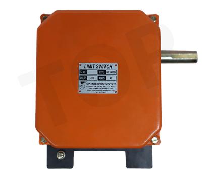
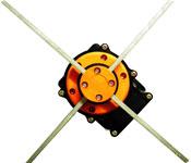
Rotary Geared Limit Switch
Body Material: |
Aluminium die cast |
Degree of Protection: |
IP-55 Confirming to IS- 13947 (Part-1)1993 |
Gear Ratios: |
1:48, 1:60 |
Drive: |
Worm Drive |
Cable Entries: |
Double break silver cadmium |
Rated Voltage Insulation: |
500 V.A.C. |
Thermal Test Current: |
10/40 Amps. |
NO. of Contacts: |
6 maximum |
Cam setting: |
adjustable |
Contacts: |
Normallyopen / Normally close
|
Introduction
Next, align the brake drum and adjust the nuts on the tie-rod such that both shoes grip the brake drum equally. Energize the power cables, this will cause the thrust rod/ end shield of the thruster to move up and the brake is released as the shoes release the brake drum. Adjust the setting bolts on both arms.
For Uniform wear of brake liners of both shoes, both arms must move equally. The setting screw of the side arm must be sdjusted such that it arrests its movement when the thruster reaches half of its stroke. Next the setting screw of the main arm is to be adjusted, such that the movement of the main arm is adjusted when the thruster reaches its full stroke.
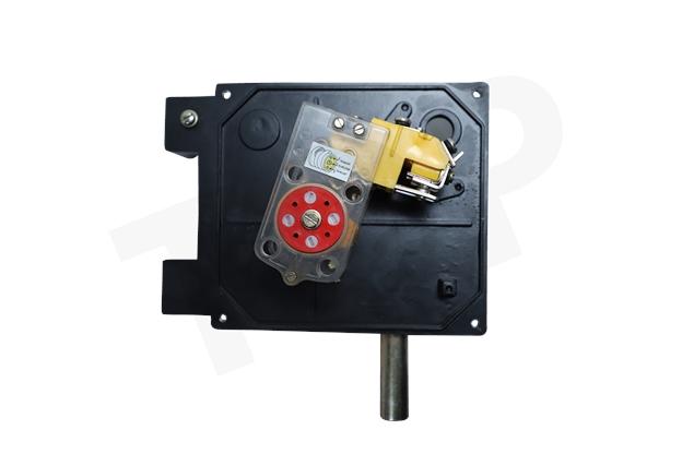
Application:
Rotary geared type limit switches are suitable for use reversing drives such as hoists, winches, rolling mills and various other mechanisms used such used in steel plants such as coke oven, feeding machinery etc.
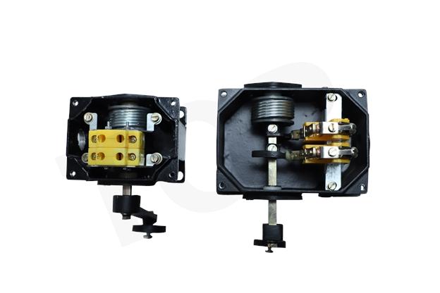
Construction:
Rotary geared type switch is basically consists of heavy duty worm gear drive. The worm gear unit is built in a cast housing fitted on main bossy of limit switch, the cam shaft which extends from behind the gear into housing, accommodation the cams adjustable actuators which are fitted on the cams. These actuators strikes the contact finger of respective contacts
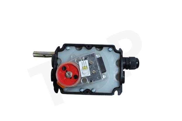
Worm Drive Switch FG
Body Material: | Black Nylon |
Cover Material Yellow: | Impact proof thermoplastic |
Protection Degree: | IP-55 Confirming to IS-13947 |
Mounting Position: | Any |
Gear Ratios: | 1:12.5, 1:25, 1:50, 1:100, 1:200 & 1:400 |
Drive: | Worm Drive |
Cable Entries: | 2, 3/4″ Conduit |
Maximum Rotation Speed: | 1200 rpm |
Contact Material: | Double break silver cadmium |
Wire Connection: | Screw terminal |
Rated Voltage Insulation: | 500 V.A.C. |
Thermal Test Current: | 10 Amps. |
Application
The new range of limit switches FG has been designed and manufactured according to safety standard are suitable for use on reversing drives such as hoists, cranes, winches and rolling mills etc.
Design:
The driving motion is transmitted by worm gear. All gears and hubs are made of low wear thermoplastic. The rotational movements are transmitted to switches by adjustable cams.
Driving cams:
Each lever has a single micrometric resister screw.This screw exclusively works on its own combined lever, excluding any mechanical contact with any other nextto it. The regulation is easily made by use of screwdriver on a register screw. The special friction system assures a rapid and precise adjustment.
Mechanical Data:
Ratios |
Effective Rotations |
Useful Rotations |
2 Contacts Model |
4 Contacts Model |
1:12.5 |
12 |
11.6 |
FG12.5P2 |
FG12.5P4 |
1:25 |
24.5 |
23.2 |
FG25P2 |
FG25P4 |
1:50 |
49 |
46.5 |
FG50P2 |
FG504 |
1:100 |
98 |
93 |
FG100P2 |
FG1004 |
1:200 |
196 |
185 |
FG200P2 |
FG200P4 |
1:400 |
392 |
372 |
FG400P2 |
FG400P4 |
Worm Drive Switch FG
Indroduction
LSR Cross 4way switch operates the control changeover. Contact of motor of moving equipment when operates with load actuates the 30mm Road of limit switch this in turn. Operates the NO/NC change-over contact elements
General Characteristics
| |||||||||||||||||||||||
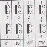
Operation
The contact operate / change-over at 90° rotations. The limit switch has 4 position 0°-90° -180° -170° operations, used for single / two speed motor control. Control switch with 300mm road from 3 to 4 position with 2 or 4 contacts.
| Description | Tune | Diagram |
| 3-position with mechanical interlock | LSR 2S | A |
| 3-position with mechanical interlock | LSR 22S |
B |
| 4-position rotary | LSR 4S | C |
| 4-position rotary | LSR 5S | D |
| 4-position rotary | LSR 5S1 | E |
| For two-speed motorcontro | ||
| 4-position with mechanical interlock | LSR 22 D | F |
Wiring Diagram A LSR 2 S With Mechanical interlock
Wiring Diagram B LSR 2 S With Mechanical interlock
Wiring Diagram C LSR 4 S Without Mechanical interlock
Wiring Diagram D LSR 4 SM Without Mechanical interlock
Wiring Diagram C LSR 4 SM 1 Without Mechanical interlock